
Custom Piling Machines, Factory Direct
Custom Piling Machines, Factory Direct


A tremie is a vertical pipe, fitted with a hopper at the top, that carries concrete to the bottom of a hole filled with water or slurry so the concrete does not mix with the fluid. This guide explains what a tremie pipe is, how tremie concrete is placed in a bored pile, and what goes wrong when the pour is not controlled.
A tremie pipe is lowered to the bottom of a drilled shaft after the reinforcement cage is in place. Concrete is fed through the hopper and flows down the pipe by gravity, pushing the water or slurry up and out as the pile fills from the bottom. The pipe outlet must stay buried in the fresh concrete the whole time, and the pour must be continuous. If the outlet leaves the concrete, fluid enters the pile and creates weak zones. The project specification sets the pipe size, concrete mix and embedment depth.
A tremie is a placing method and a piece of equipment: a vertical pipe through which concrete is discharged at the bottom of a hole or excavation that holds water or drilling slurry. The word comes from the French for hopper, which is the funnel fitted at the top of the pipe.
In everyday site talk, “the tremie” means the pipe, and “tremie concrete” means the concrete placed through it. Dropping concrete through water or slurry from the top washes the cement out and separates the aggregate. The tremie avoids that by delivering the concrete below the fluid, where it can push the fluid aside.
The same method also forms underwater slabs, called tremie seals, inside cofferdams. This guide covers the use that matters to bored pile contractors: concreting the pile shaft after the hole has been drilled.
A tremie is used wherever concrete must be placed below a fluid level. In foundation work that usually means these cases:
Bored piles are also called drilled shafts or drilled piers, and large-diameter ones are sometimes called caissons. The method described here applies to the first case in the list above: a rotary-drilled shaft that is concreted from the bottom up.
A tremie pipe system is a string of steel pipe sections with a hopper at the top and a plug or seal at the bottom. The table lists the parts you will find on most systems.
| Part | What it does |
|---|---|
| Pipe sections | Steel tubes, often 1 to 3 m long, joined to reach the base of the hole and removed one by one as the pour rises |
| Joints or couplings | Connect the sections and must be watertight so slurry cannot enter |
| Hopper | The funnel at the top that receives concrete from the pump, chute or truck |
| Lifting cap | The top fitting that the crane uses to hold and raise the string |
| Plug (pig) or sealed gate | Keeps water or slurry out of the pipe until the first concrete arrives |
| Bottom section | The lowest length, which meets the most wear and discharges at the base of the pile |
The three common joint types are threaded, flanged and quick coupling. Threaded joints are simple and strong. Flanged joints bolt together and take longer to assemble. Quick couplings are the fastest to fit, but they need a good seal and regular inspection.
Pipe size follows the pile and the concrete. Several state transportation specifications call for a pipe at least 10 inches (about 250 mm) in diameter, and at least six times the size of the largest aggregate. Aluminum parts should not touch the concrete, because aluminum reacts with the cement.
A tremie pipe works by keeping the concrete inside a closed, full pipe until it is below the surface of the fluid, and then letting it flow out at the bottom. Gravity moves the concrete down, and the rising concrete pushes the lighter fluid upward.
Once the concrete is flowing, one rule decides the rest of the pour.
Keep the outlet below the surface of the fresh concrete.
One state specification asks for the discharge end to stay 5 to 10 feet (about 1.5 to 3 m) deep in the concrete before the pipe is lifted, and other sources quote values in a similar range. Your project specification gives the number to follow.
A tremie concrete pour is the last stage of bored pile construction, and the hole must be right before it starts. The usual order is as follows.
The pour has to run above the final cut-off level. The top of the pour collects sediment and weak concrete that must be cut away, so the pile needs sound concrete up to the level the design requires.
A tremie is needed when the hole is wet, and it is optional when the hole is dry. Dry holes stay free of water and do not cave in, and wet holes hold water or slurry that supports the walls or cannot be pumped out.
| Condition | Typical situation | How concrete is placed |
|---|---|---|
| Dry hole | Water table below the base, stiff soil that does not cave | Concrete can be dropped through a centering chute, if the specification allows it |
| Wet hole, slurry-supported | High water table or sandy soil that would cave | Tremie pipe or concrete pump pipe to the base |
| Wet hole, with casing | Caving soils with water, casing advanced with the drilling | Tremie or pump pipe, with the water in the casing displaced by the concrete |
Drilling fluid and casing choices belong to the contractor and designer. Specifications also vary on whether water, polymer or bentonite slurry is allowed, so follow the project documents.
Tremie concrete must flow easily, resist segregation and stay workable for the whole pour. It flows through the pipe and the cage by gravity, so a stiff mix will block the pipe or leave voids around the steel.
State drilled shaft specifications typically set a high target slump, often in the 8 to 9 inch range (about 200 to 230 mm). They also require the slump to stay above a minimum, commonly about 4 inches (100 mm), until the pour is finished. Retarders are used on long pours so that the concrete does not stiffen before the pour ends.
The concrete supply must be planned too. Trucks need to arrive on schedule so the pour is not interrupted, and the contractor should know the volume needed for the pile before it starts.
Most tremie pour defects come from a lost seal, a stopped pour or poor concrete. The table shows the common problems and what prevents them.
| Problem | Typical cause | How to prevent it |
|---|---|---|
| Slurry or sediment inside the pile | Pipe outlet lifted out of the concrete | Track the concrete level and the pipe length, and keep the outlet buried |
| Blocked pipe | Stiff or low-slump concrete, or a stopped pour | Keep the slump up and supply the concrete continuously |
| Voids or honeycomb | Concrete too stiff, or the cage too tight for the aggregate | Check the mix and the bar spacing before the pour |
| Cage lifted or shifted | Cage not held down, or the pipe lifted too fast | Hold the cage down, and raise the pipe slowly |
| Weak concrete at the base | Sediment left at the bottom of the hole | Clean the base, and clean again after the cage is set |
| Pile narrower than design | Casing pulled too fast, or concrete level dropped | Keep a head of concrete above the casing, and stop and add concrete if the level falls |
If the pipe does leave the concrete, one state specification requires the end to be re-sealed, filled with concrete and pushed back into the concrete by at least 10 feet before pouring continues. Whether the pile is accepted is then decided by the engineer and by testing.
Most defective piles are caught by checking before the pour and recording during it. The checks below follow what many agency specifications ask for.
| When | What to check |
|---|---|
| Before drilling ends | Depth, diameter and plumb, using marks on the kelly bar and a plumb check |
| Before the cage goes in | Base cleanliness, using a weighted tape to measure sediment, and slurry condition |
| Before the pour | Cage held and centered, pipe watertight and sealed, concrete supply and slump confirmed |
| During the pour | Concrete level and outlet depth, with a weighted tape, plus the volume delivered |
| After the pour | Placed volume against the theoretical volume of the shaft, which can reveal voids |
| On the finished pile | Integrity testing, such as pulse echo or cross-hole sonic logging, and coring or load tests when specified |
Keep a pour log with the time, truck volume, slump, the length of pipe in the hole and the measured depth to concrete. The FHWA drilled shaft construction manual (FHWA-NHI-10-016) sets out many of these checks in detail.
The three ways to place concrete in a shaft are free fall, a tremie pipe, and a concrete pump with a pipe to the base. The table compares them.
| Method | Where it works | Main limit |
|---|---|---|
| Free fall | Dry holes only, through a centering chute | Concrete must not hit the walls or the cage, and the fall height is limited |
| Tremie pipe | Wet and dry holes, cased or uncased | Needs a crane to hold the string, and the outlet must stay buried |
| Pump pipe to the base | Wet and dry holes | Needs watertight joints, and sway of the pipe must not disturb the fresh concrete |
A pump pipe is used much like a tremie, so the same embedment rule applies. Many sites feed the tremie hopper from a pump or a concrete bucket.
A full tremie string is heavy, so the crane, lifting cap and lines must be rated for the pipe, the concrete inside it, and the loads while the string is lifted. Check the rating before the first pour, not during it.
The rotary rig makes the hole, and the tremie fills it, so the quality of the hole sets what the tremie can achieve. The rig controls the diameter, the depth, the position and the plumb of the shaft, and the cleaning bucket prepares the base.
A well-drilled hole makes the pour easier: a straight shaft lets the cage hang centered, and a clean base keeps sediment out of the concrete. The kelly bar carries the tool and shows the depth, as described in our guide to the kelly bar, and the types of bored pile are covered in types of piling.
Kaiao builds the drilling side. The table shows the rated ranges of two of our crawler rigs. These are maximum rated values, and the real depth depends on the bar configuration and the ground.
| Rig | Hole dia. / depth | Torque | Weight |
|---|---|---|---|
| Large crawler foundation rig | Φ1800 mm / 40–50 m | 150–170 kN·m | 42–50 t |
| Interlocking kelly bar rig, crawler type | Φ1500–2200 mm / 15–35 m | 70–170 kN·m | 23–33 t |
See the foundation drill rig for the large rig, and the wider range under rotary drilling rig. Tengzhou Kaiao Construction Machinery Co., Ltd. makes the drilling equipment only. Tremie pipes, concrete and the pour itself are the contractor’s part of the job.
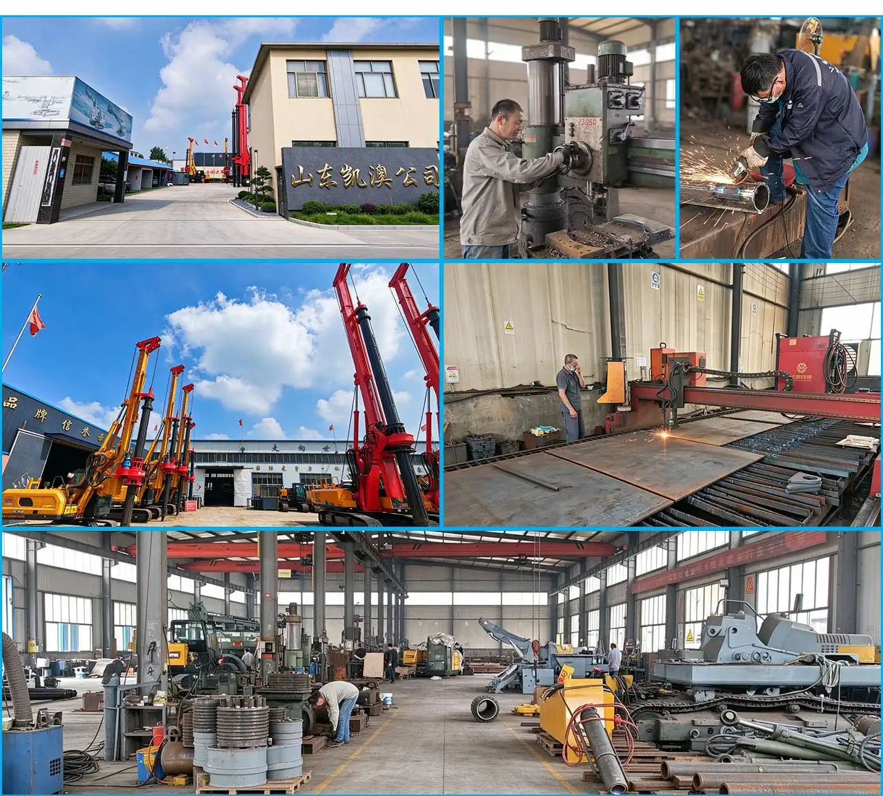

Our own factory in Tengzhou, Shandong: development, production, sales, after-sales and custom work all happen under this roof.
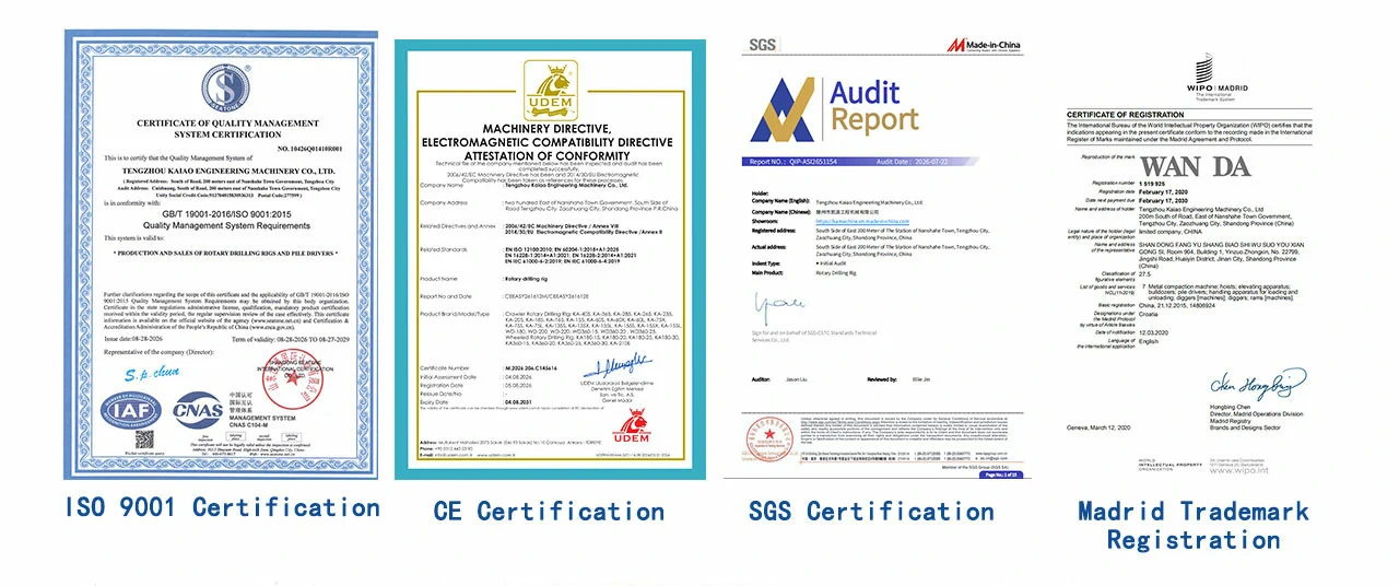

ISO 9001 and CE certification, plus patents that include wireless remote control and automatic drilling on rotary rigs.
Learn more about Kaiao.
A tremie is a vertical pipe with a hopper at the top that delivers concrete to the bottom of a hole or excavation filled with water or slurry. The concrete flows out below the fluid and pushes it aside, so the cement does not wash out. The name comes from the French word for hopper.
A tremie pipe is a string of steel pipe sections, joined with watertight couplings, that is lowered to the base of a bored pile or similar excavation. A hopper at the top receives the concrete, and a plug or seal at the bottom keeps fluid out until the first concrete arrives. Sections are removed as the pour rises.
Tremie concrete is concrete placed through a tremie pipe below the level of water or slurry. It needs a high slump, a mix that resists segregation, and a supply that does not stop. State drilled shaft specifications typically set a target slump around 8 to 9 inches and require it to stay above about 4 inches during the pour.
A tremie is used because concrete dropped through water or slurry washes out and separates, which weakens the pile. The pipe delivers the concrete at the base, where it pushes the fluid upward. In a dry hole, a centering chute may be allowed, but a wet hole needs a tremie or a pump pipe.
The pipe outlet should stay buried in fresh concrete throughout the pour, and the project specification sets the depth. One state specification asks for 5 to 10 feet, about 1.5 to 3 m, before the pipe is lifted, and other sources quote similar values. A weighted tape is used to measure the concrete level.
Tremie pipe size depends on the pile and the concrete, and many state specifications call for at least 10 inches, about 250 mm, and at least six times the largest aggregate size. Sections are often 1 to 3 m long. The pipe must be wide enough for the concrete to flow freely.
The plug, often called a pig, separates the first concrete from the water or slurry inside the pipe. It slides down ahead of the concrete and is released at the bottom, so the first batch is not diluted. A sealed gate at the bottom does the same job on some systems.
If the pipe outlet leaves the concrete, slurry or water can enter the pipe and mix into the pile, which leaves weak zones. The usual response is to re-seal the pipe, refill it, and push it back into the concrete before continuing. The engineer then decides on testing and acceptance of the pile.
You need the target hole diameter and depth, the ground conditions, the groundwater level, the site access and the project destination. With those details, Kaiao can tell you honestly which machine fits. A soil report and site photos make the recommendation more accurate.
Planning bored piles? Send us the hole diameter and depth, ground conditions, groundwater level, site access and destination, and we will tell you honestly which rotary rig fits.
Scan with WeChat. On a phone, save the image and scan it from your album.
Send us your project details and we will reply with a recommendation and a quotation.
Send an Email